How do you use a lead gauge?
FYOU PMEC, One Stop Shopping for Threading and Gaging Solutions!
FYOU PMEC’ API Thread Gauges、Premium Connection Gauges ,and ANSI/ASME Thread Gauges have been used worldwide and receiving the highest quality reputation. And our supplier plants are licensed to API Spec5B, API Spec7-2 and API Spec11B.
FYOU PMEC, supply a complete line of Thread Gauges listed in the API Spec 5B ,API Spec 7-2, and API Spec 11B. Also, we provide its measuring gauges. To find out more information on our products, please contact us by E-mail: sales@fyougauges.com. We will provide you the best possible solutions for you as quickly as we can.

1.Definition
Lead shall be defined as the distance from a point on a thread to a corresponding point on the next thread turn, measured parallel to the thread axis. Lead tolerances are expressed in terms of “per inch” (“per millimeter”) of threads and “cumulative,” and lead errors must be determined accordingly. For interval measurements over lengths other than 1 in. (25,4 mm) the observed deviation should be calculated to the per in. (per mm) basis. For cumulative measurements, observed deviations represent the cumulative deviation.
2. Gauge Contact Points
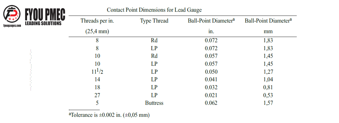
The contact points of lead gauges shall be of the ball point type with diameters in accordance with the following table. For line pipe and round threads, the diameter of the contact points are such that they contact the thread flanks at the pitch cone, approximately, rather than the minor cone. For buttress threads, the dimensions of the contact points are such that they simultaneously touch the root and the 3 degree flank of the thread.
4.Lead Gauge
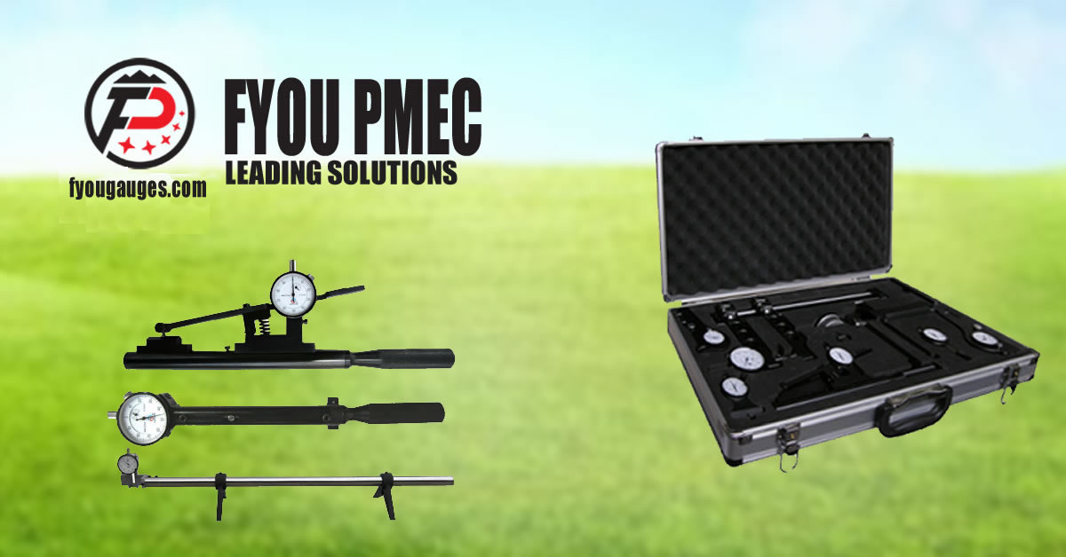
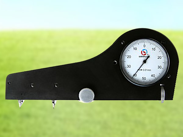
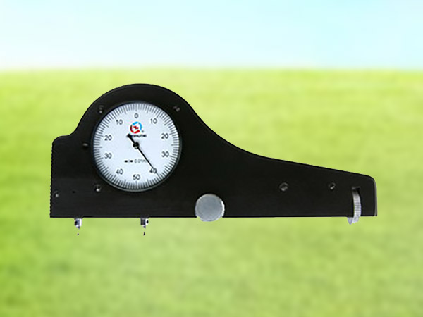
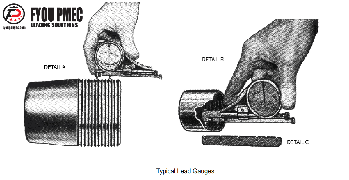
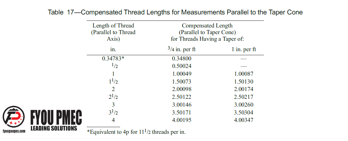
The lead of all external or internal threads in sizes 41/2 and larger shall be measured with a lead gauge of the type illustrated as bellow, Detail A. The lead of all internal threads in sizes smaller than 4 shall be measured with a lead gauge of the type illustrated as bellow, Detail B. Lead gauges shall be so constructed that the measuring mechanism is under strain when the indicator is set to zero by means of the standard template (as bellow, Detail C). The standard template shall be so constructed as to com- pensate for the error in measuring lead parallel to the taper cone instead of parallel to the thread axis, according to the values shown in Table 17. The distance between any two adjacent notches of the template shall be accurate within a tolerance of 土0.0001 in. (土0,003 mm), and between any two non-adjacent notches within a tolerance of 土0.0002 in. (0,005 mm).
5.Adjustment of Gauges
Before use, the fixed ball point shall be set to provide a distance between points equal to the interval of threads to be inspected, and the indicator set to the zero position when the gauge is applied to the standard template. When applying the lead gauge to buttress templates, care must be taken to ensure the contact points engage the root and the 3-degree flank.
6.Procedure (Lead Gauge)
The ball points of the gauge shall be placed in the proper thread grooves and the gauge shall be pivoted upon the fixed ball point through a small arc on either side of the correct line of measurement. The minimum fast (+) or maximum slow (-) reading is the deviation in lead. On buttress casing threads, slight pressure shall be exerted on the gauge so that the fixed ball point remains simultaneously in contact with the 3-degree flank and root of the thread during the measurement. The pressure is applied toward the small end on external threads and toward the large end on couplings.
How to Order?
When you order, please let me just know the thread type and range need be measured, we will provide you the best solutions and best quotations. More details or any questions please contact: sales@fyougauges.com or WhatsApp/Wechat: +86 13962168423
