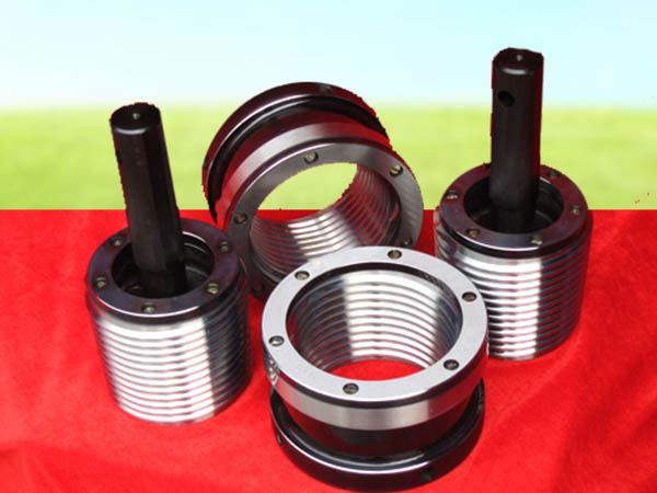
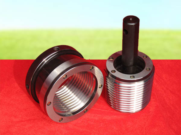
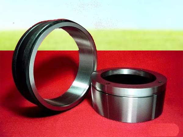
FYOU PMEC is The Leading Gage Solutions Server in China. The premier lead in providing highest quality of API Oil Country Gauges, including API Working Gauges, API Master Gauges. But How to USE API Plug Gauges to Measure API Tubing &API Casing & API Line Pipe Couplings?
Any question and request about the API Gauges Please contact :sales@fyougauges.com

1. API Spec 5B Working Gauges, which are used to measure Measure API Tubing &API Casing & API LinePipe Couplings

2. API Gauges Design Description
It is common to find two gage designs throughout the industry. One is known as “Shoulder Design”, and one is known as “Removable Keys Design”. Both designs have their benefits, and both get the job done, which one you use is purely a matter of preference. Both designs provide Basic, Minimum and Maximum scribe lines for visual verification of standoff; physical measurements may also be taken when necessary. API Specification 5B states that the required standoff between the API plug gage and a coupling is:
8 TPI Tubing & Casing = A ± 1P
10 TPI Tubing = A ±1‐1/2P
Line Pipe (All Pitches) = A ± 1P

3. API Specification 5B defines “A”.
API Specification 5B defines “A” by the number of turns. Since each turn is 1P, we can break “A” down to a decimal value that is more useful when gaging. For example, a 4”‐8 External Upset Tubing has an “A” value of 2 Turns. Since each turn is 1P, and 1P for 8TPI is 0.125” (1/8), the decimal equivalent of “A“ is 2 x 0.125” = 0.250”. Since this has a tolerance of ±1P, we know that the standoff for a 4”‐8 External Upset Tubing is 0.250” ± 0.125”
4. How to Use?
When gaging the coupling, the plug gage should screw into the coupling until hand tight; at that point the face of the coupling must fall in between the Minimum and Maximum scribe lines in order to pass as a good part. If required, a direct measurement can also be taken. Using the “Shoulder Design” plug, the standoff can be measured between the face of the coupling and the shoulder, this dimension should be “A” with a tolerance of ±1P (8 TPI Tubing and Casing and All Line Pipe) or ±1‐1/2P (10 TPI Tubing). Using the “Removable Keys Design”, the standoff can be measured from the back face of the plug gage to the face of the coupling. When using this method, it is important to note the dimension scribed onto the back face of the gage “Distance from back face to V.P.”. The required standoff from the back face of the the plug gage to the face of the coupling should be “A”+Distance from Back Face to V.P” with a tolerance of ±1P (8 TPI Tubing and Casing and All Line Pipe) or ±1‐1/2P (10 TPI Tubing)
5. Schematic Diagram
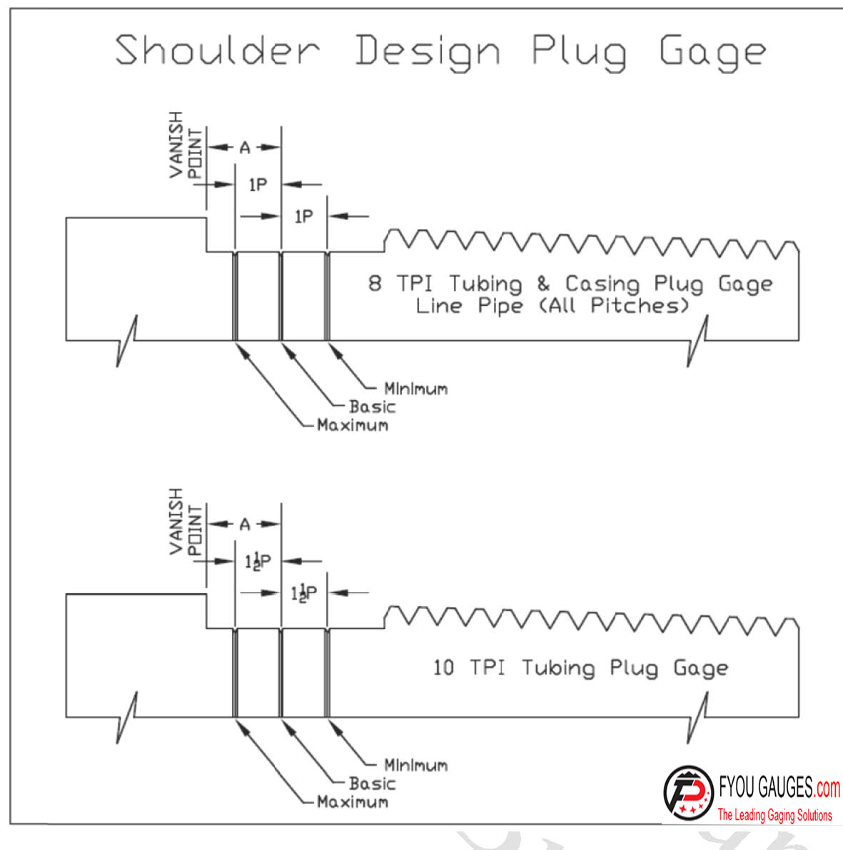
Removeable key Design Plug Gage
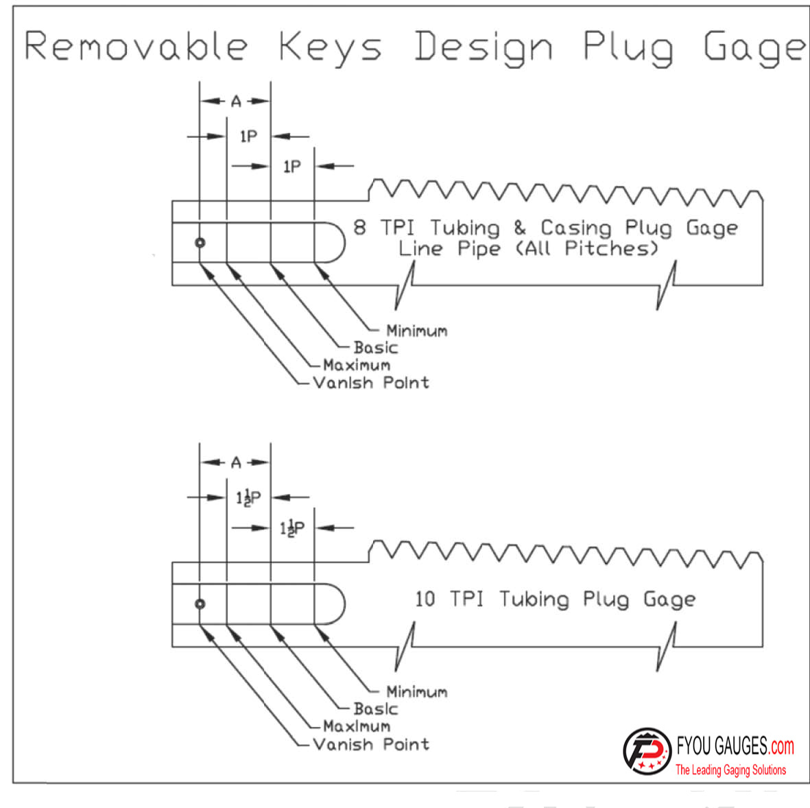
Note:Standoff information provided is based on nominal condition and is for reference only. API 5B requires that standoff to the coupling is calculated using actual size of working and master gauges; Using the formula A+(S1– S). These vaues can be located on the certification received for each gage.S is the required staandoff listed for the work plug to master ring, and S1 is the actual staandoff for the work plug to masteer ring. When available,these values should be used in order to propperly adjust the gage standoff inn order to maintain compliance to API 5B

Any question and request about the API Gauges Please E-mail to :sales@fyougauges.com

